top of page

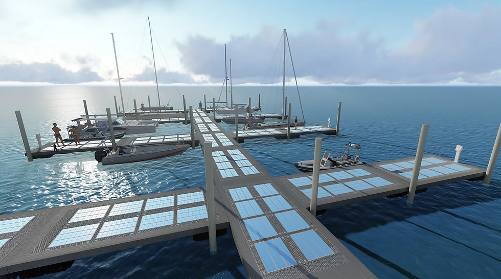
Shown is a rendering from PowerDocks, a partner company of E2SOL. These marinas will face loads from humans to golf carts (common in Europe). Therefore, I had to design each solar module to withstand a load of up to 1000 lbs while keeping cost as low as possible.
Design Requirements
The 435 W Sunpower solar panel module with aluminum framing has an open backside. Since some clients might have exposed sections of their docks to place these under, the worse case scenario would be that the module is only fixed by the aluminum frame. The support structure should not interfere with the terminals (shown in black in the image) and an additional inverter underneath the module.
I brainstormed 3 ideas for a support structure to mount underneath.
Laser-cut truss cross sections
Triangular or circular tubing bound by weldments or concrete
Corrugated steel
To minimize manufacturing and material costs, I selected corrugated steel.


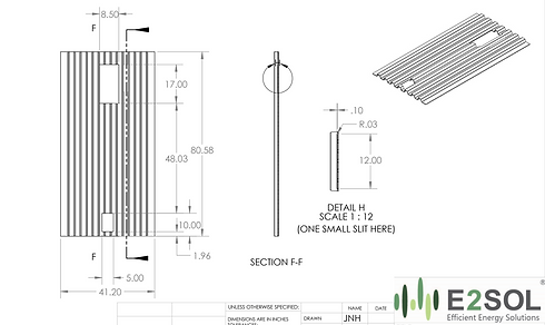
This is the first iteration of the design. The steel would be waterjet to create the cutouts that would house the electronics and then stamped with custom tooling. Detail E shows slits that would allow it to slot in to the aluminum framing.
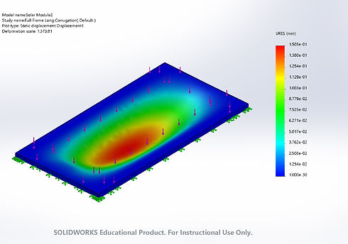
From the SolidWorks simulation shown above, we can see a max deflection of around 0.05mm under 500 lbf with AISI 1020 Cold Rolled Steel. Due to the cutout to house electronics, stress concentrates at the top in red. Under 1000 lbf, and when fixed at all edges, a 0.1mm max displacement was observed.
After much discussion with my boss and with fabricators, I produced a second iteration of the design where the direction of corrugation is flipped. The wires could then be channeled through instead of making large cuts to compromise the structure. The tolerances for mounting it through press-fit slits would require expensive, precise machining. In this design, mounting holes can be drilled into the left and right flaps.
When simulated with the same corrugation geometry, material, and sheet metal gauge under 1000 lbf load, a similar max deflection of 0.15mm was observed.


I began to optimize the geometry of the corrugation pattern to reduce deflection as much as possible. I performed around 15 different simulations with 0.1345 thickness AISI 1020 Cold Rolled steel. I changed 3 variables and found the following decreased deflection the most: 70 degree angle, 2" trough width, and 1.8" peak width, as shown above.
I was able to achieve deflection as low as 0.046mm with steel! After reaching out to over 20 sheet metal fabricators in MA, RI, and NC, I learned the hard way that creating custom metal stamping or rolling tooling for a couple prototypes is really expensive if we're not doing high volume manufacturing yet. So I found some local fabricators who can thermoform ABS or mold FRP! Pictured above is a simulation of 1000 lbf on ABS material, achieving 0.7mm deflection, which is surprisingly successful! Going forward, we'd test the long-term durability of working with plastics if they are similarly durable but cheaper.
bottom of page