PULTRUSION MACHINE
Technical University of Denmark, 2023
Waste from decommissioned wind turbine blades is a major issue, especially in Denmark, where wind energy composes almost 50% of the energy mix. I spent 5 months at the Technical University of Denmark (DTU) Wind and Energy Systems lab, with Professor Ali Sarhadi's additive manufacturing lab. This lab investigates the new ways of manufacturing blades--through robotic arm 3D printing fiber reinforced polymer (FRP) composites. A robot arm can be used to repair blades or manufacture unique shapes that traditional resin cast molds can not. I conducted a literature review on the potential for Biomimetic blade designs that 3D printing can open the doors to!
This page, however, focuses on my work with assessing the manufacture of a spar cap--the structural beam on the interior of the blade. How can we design a more circular turbine blade?


The Problem
Wind turbine blades, typically composed of resin, are very difficult to recycle. At the DTU FiberLab, they shred resin-based blades and consider using the material for future reinforcement in blades or building materials (Pictured). However, the quality has been jeopardized and the blade is downcycled.


Machine Design:
Modular Pultrusion Test Bed
Labelled Solidworks drawing
Pultrusion is a repeatable manufacturing process for constant cross-section FRP components. It involves the pulling of the fibers through a hot die, which forms the FRP into shape. Thermoplastic pultrusion, which uses thermoplastics as the matrix polymer through which the fibers are pulled, is a relatively newer form of pultrusion, compared to thermoset pultrusion, which uses resin.
-
First, the fiber and matrix (polymer) are spooled together. This is through commingling, or combining together with an airjet, using a novel method I prototyped.
-
This machine will be modular. Therefore, an optional shelf for a resin bath is positioned before the die.
-
The die consists of a pre-heater with a larger cross section, which tapers into the heated die, and finally a cooling die. The die is mounted on a linear sliding beam with a load cell to measure pulling force.
-
The cooling machine sits underneath the die, water cooling the cooling die.
-
The distance between the end of the die and puller is adjustable, for compactness, to ensure enough air cooling before the puller.
-
A geared DC motor drives the puller, which contains a spring-loaded lead screw for proper clamping force.
-
A smaller stepper motor sits on a supplementary table to spool the final thin pultruded component.


1
2
3
5
4
6
7
01
Commingler
The commingler consists of 3 3D printed components that can be glued together, a dual guide, a single eyelet, and a chamber where compressed air will be pumped through 3 inlets. This allows for rapid prototyping and iterative design, adjusting length, diameter, and other parameters to optimize mixing of the fiber and polymer.


03
Die
The die consists of a a pre-heater (not pictured), heated die (left), and cooling die (right). The die will be heated using 300C heat canisters in the 6 bore holes shown. Then, cooling pads will cool the die to 100C from the cooling machine. The taper angle, length, and placement of heating and cooling elements were optimized using COMSOL.
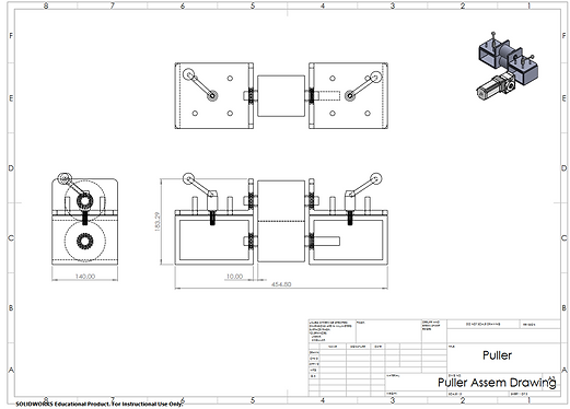
06
Puller
The puller consists of two custom polyurethane coated spools on bearings in aluminum housing. A spring-loaded lead screw allows precise adjustment of compression force to hold the component between the spools. The puller is actuated by a belt drive from a geared DC motor.